A multimeter is crucial for troubleshooting an industrial sensor. We’ve asked the experts here at Automation Products Group, Inc. (APG) to provide a guide on how to use a multimeter to troubleshoot your industrial sensor and get it working properly in no time!
What is a Multimeter?
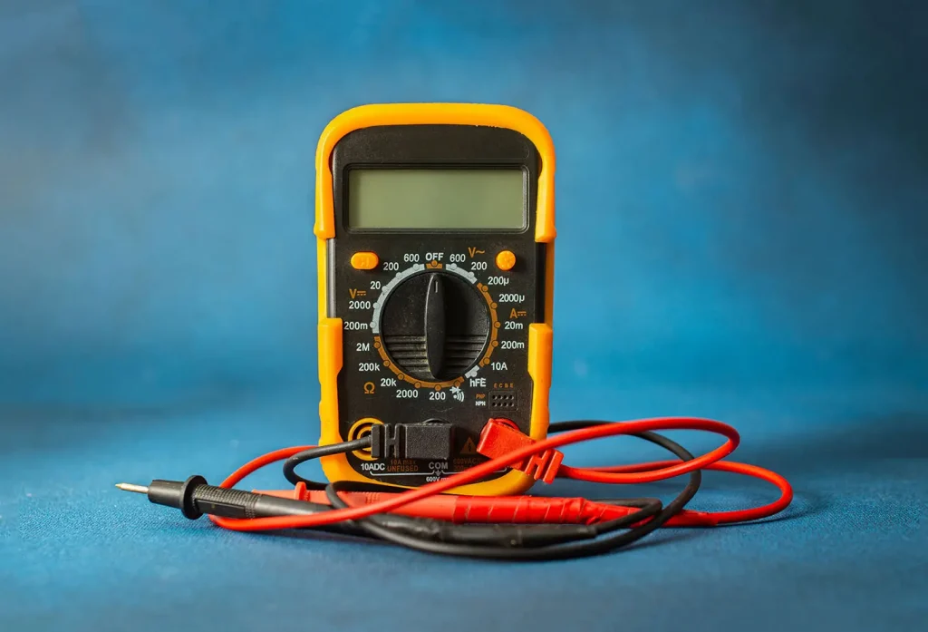
A multimeter is an electrical instrument used to test circuits. Multimeters can measure multiple electrical properties, such as voltage, current, resistance, and continuity. This flexibility makes them vital in troubleshooting, as they locate and identify problems in an industrial sensor.
On a multimeter, several settings are available to test for different areas. The most common settings are:
- For current, both alternating (AC) and direct (DC), measuring from micro- or milli-amps to amps.
- For voltage, both AC and DC, measuring from millivolts to hundreds of volts.
- For resistance, measuring from ohms to megaohms.
More advanced models have additional settings to measure capacitance, decibels, frequency, inductance and/or temperature.
How Does a Multimeter Work?
Multimeters are designed using fundamental electric circuit theory. Ohm’s Law states a fixed relationship between voltage, current, and resistance between any two points in a circuit. The formula is I=V/R, with I being the current, V the voltage, and R the resistance. So, the current is equal to voltage divided by resistance.
Multimeters use two known quantities to solve for the third, unknown, quantity:
- To measure resistance, the change in voltage created by a small current is measured.
- To measure voltage, the movement created by a quantifiably small current through known resistance is measured.
- To measure current, a similar movement is measured through a resistance at a specific ratio to the current in question.
Further quantities mentioned above (capacitance, etc.) are measured using similar techniques.
How to Use a Multimeter
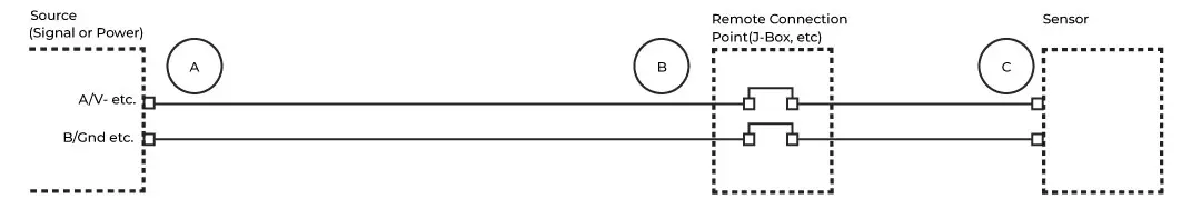
Running three simple tests with the multimeter can help pinpoint the problem in your sensor. Use the diagram below for reference as you move through the tests.
Multimeter Continuity Test
Appliance components need continuity to function correctly. A multimeter continuity test determines if there’s a continuous flow of electricity and ensures that the wires are connected correctly.
Step 1: Disconnect the wires for the sensor at its power source (Point A in the diagram).
Step 2: Plug the black probe into the COM (common) port on your multimeter. Plug the red probe into the VΩ port.
Step 3: Set your multimeter to Continuity. The symbol looks a bit like this: •))).
Step 4: Connect the red probe to the + wire going to the sensor and connect the black probe to the ground wire going to the sensor.
Note: Communication wiring can vary according to the sensor’s output and your control system. Please consult your sensor’s user manual or manufacturer for more information.
Step 5: If the multimeter registers a reading, your circuit wiring is intact. If the multimeter doesn’t register a reading, then something’s wrong with the wiring. Repeat these steps along the various sections of the circuit between the source and sensor to isolate the problem.
Step 6: This process should also be performed with your sensor’s communication wiring.
How To Check Voltage with a Multimeter
Having established the continuity of the circuit, let’s check the source voltage, but not at the source.
Step 1: Reconnect the sensor’s power source.
Step 2: Disconnect the power wires at the sensor (Point C in the diagram) or connection point closest to the sensor (Point B, if the cable to your sensor cannot be disconnected at the sensor).
Step 3: Maintain the same probe and multimeter connections.
Step 4: Connect the red probe to the incoming + wire, pin, or terminal, and the black probe to the ground wire, pin, or terminal.
Step 5: Select the DCV value on the multimeter that is closest to, yet bigger than, the source voltage.
Step 6: Turn on the power source.
Step 7: Verify that the voltage at the sensor is within the range suggested in the user manual. If so, this eliminates source voltage as the problem. If not, the voltage source is a problem. Turn the power source back off.
How to Check Resistance with a Multimeter
Next, we’ll check circuit impedance or resistance. In general, circuit impedance is only critical for communication circuits (Modbus, Hart, etc.), but checking can still be instructive for other circuits.
Step 1: Reconnect the power wires at the sensor.
Step 2: Disconnect the communication wires for the sensor at the source (Point A).
Step 3: Maintain the same probe and multimeter connections.
Step 4: As before, connect the red probe to the + wire going to the sensor, and connect the black probe to the ground wire going to the sensor.
Step 5: Many sensors using communication protocols require a minimum of 150Ω to 180Ω, so choose the Ohm value on the multimeter that is closest to, yet bigger than, 200Ω. If the circuit impedance is less than that recommended by the user manual, then add an appropriate amount of resistance to the circuit.
Step 6: If the multimeter doesn’t register the impedance, select the next highest denomination of Ohms. If the circuit’s impedance is too high (and not infinite), something will need to be removed from the circuit (switch to a smaller wire size, too many intermediate junctions, etc.).
Sensor Still Not Working?
If these steps haven’t helped you identify and isolate the problem, the sensor itself might be a problem. If you need a new sensor, check out APG’s selection of high-quality sensors. We make sure our products are reliable and are always available to support our customers. You can contact us. One of our representatives will get back within 24 hours!
WRITTEN BY

Sami T.
Sami Thompson is APG’s Marketing Technical Writer and has been with the company since 2022. With a master’s degree in English from Utah State University and a 40-page thesis publication under her belt, Sami has a demonstrated strong writing background. In her free time, Sami enjoys reading and birdwatching.