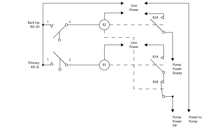
Backup pump control is a critical part of any pump control application, ensuring that failure does not result in a potentially hazardous overflow or the unwanted emptying of a tank. Ideally, back up sensors work independently from the pump control system, so that failure of the primary controls will not disable them.
This means basic control features such as hysteresis must be built into the sensor. Float switches, a popular choice for backup pump control, rarely have the features necessary to work independent of the pump control system. Despite feature deficiencies, float switches remain popular due to the low cost.
Two of the float switches that can work independent of a control system are the KA-2H (2H) and the KA-2L (2L) cable suspended float switches. So we wanted to show you how to set one up for backup pump ontrol.
The 2H is designed for high alarm and pump down applications, while the 2L has a low alarm and pump up features. Each one has mechanical hysteresis built in it, and can be used without a controller or PLC. In this fill control example, the 2L is the primary sensor, and the 2H will back it up.
Note: The contacts in the KA-2L and KA-2H are high performance miniature float switches. Because the float switch will be immersed in liquid, it is not recommended to switch pump motor currents directly through the KA-2L or KA-2H. Rather use a heavy-duty relay or contactor respectively between the 2L, 2H contacts and the pump.
All wires on the 2L and 2H are black with the conductor number printed in white on the wire jacket.

Wiring the KA-2L and KA-2H
Note: If the pumps use three phase power, use heavy duty three pole switch contacts. Each contact should be rated to carry the voltage and current required by the pump’s horsepower rating.
The 2H is an example of a float switch that, when used for back up pump control, will prevent a tank from overflowing and shut the pump off with the liquid at a safe level. The float switch works by reversing the pump until a safe level has been reached. The built-in hysteresis allows the pump to reverse at the high level and stay on until at the lower level.
Let us know if you have any questions about how this works, or how to properly wire the float switches and the pump. Our application engineers are ready and willing to help!