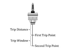
 In addition to the analog 4-20mA output, our IRU series ultrasonic sensors can be purchased with 2 NPN trip points. Fundamentally these are switches built into the ultrasonic sensor that can be used to drive a relay or contractor. Through the programming software, these NPN trip points can be configured in a variety of ways that can be used to control things like pumps and alarms.
The following settings are used to control how the NPN trip points work.
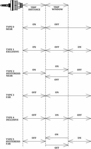
All the logic in the IRU ultrasonic sensors is found in the trip types. There are five trip types, each designed for common liquid level control tasks. These can eliminate the need for a controller, as the sensor can pass these signals directly to a relay or a contactor.
Download Ultrasonic Level Sensor Datasheets & Manuals Here
 Trip Type 0 or “Near”
The switch is closed (on) whenever the level is between the face of the sensor and the first trip point. With type 0, the trip window setting is irrelevant. Type zero is often used to trigger a high level alarm.
Trip Type 1 or “Exclusive”
The switch will be closed (on) whenever the level is between the face of the sensor and the first trip point OR when the level is farther away than the second trip point. Type 1 can trigger an alarm if levels are too low or too high.
Trip Type 2 or “Hysteresis Near”
The switch will always be closed (on) when the level is between the sensor and the first trip point, and the switch will always be open (off) when the level has moved beyond the second trip point.
The critical action in type 2 is called hysteresis, and happens in between the first and second trip points. It means that if the level is high, dropping from the section between the sensor and the first trip point, the switch will stay closed (on) until the second trip point is reached. If the level is low, and rising from the section between the second trip point and the bottom of the tank, the switch will stay open (off) until the level reaches the first trip point.
Typically this is used to control a pump for emptying a tank. The hysteresis keeps the pump from switching rapidly between on and off if the level is sitting right at one of the trip points. This is called “chatter.”
Trip Type 3 or “Far”
The switch is closed (on) whenever the level is beyond the first trip point. With type 3, the trip window setting is irrelevant. Type three is often used to trigger a low level alarm.
Trip Type 4 or “Inclusive”
The switch will be closed (on) whenever the level is in the trip window, between the first trip point and the second trip point. When the level is farther away than the second trip point, or closer than the first trip point, the switch is open (off). Type 4 is often used to communicate that the level is within a certain zone of the tank.
Trip Type 5 or “Hysteresis Far”
Like type 2, this option provided hysteresis, but because the closed (on) position is at the bottom of the tank, this would be typically be used to control a pump for filling the tank.
Perfectly clear, right? Let us know if you need help deciphering any of this. Our Measurement Experts would love to help you make sense of these settings, or even go through the programming steps with you.